-40%
Meyer 16523 Road Pro RPBF Mounting Frame Carton for 27K-33K GVW Trucks
$ 350.06
- Description
- Size Guide
Description
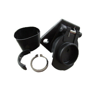
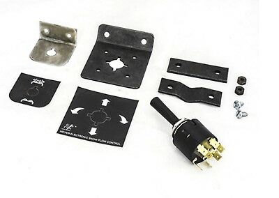
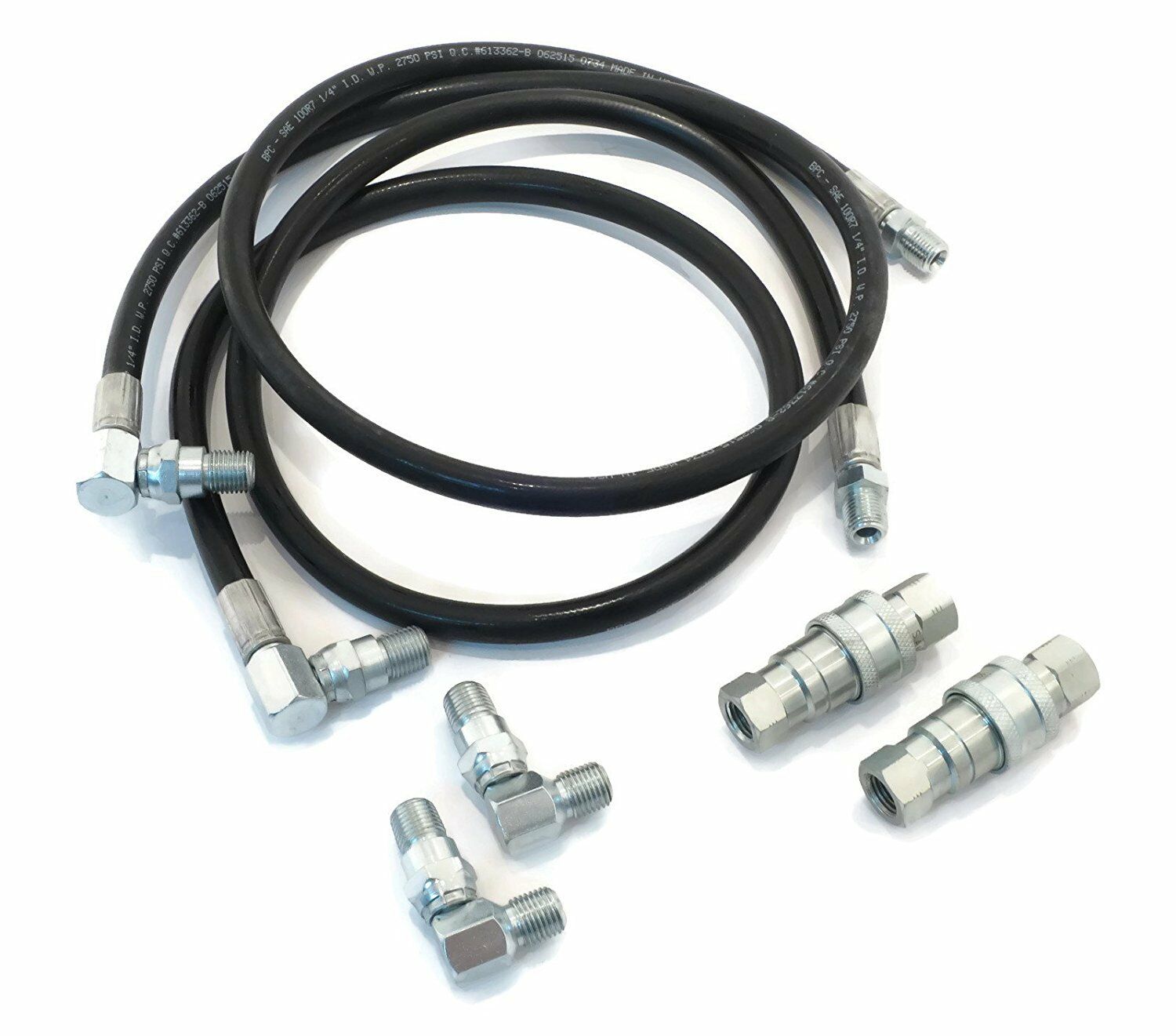
Please see parts list in pictures for part numbers this package includes. Items 1-8 on the parts diagram are all included. Contact us if you have any questions about fitment or shipping.This is old-new stock. Parts withing packaging are 100% brand new OEM Meyer parts that have never been installed. Package exterior may show signs of wear from storage. This package does not include parts not listed. These parts come with mounting hardware. Please call us if you need installation instructions or any other info!
Thanks!
Installation Instructions for this mount are below:
This is a universal mounting which is adaptable to vehicles with a GVW rating from 27,000 to 33,000 lbs. Cutting, welding, and drilling are required for all installations of this mounting.
A. Remove truck bumper. It is probable that any original bumper brackets will not be reused. This will depend on each vehicle’s front frame configuration. The bumper will be sandwiched between the Bumper Mounting Plate (6) and Bumper Channel (7).
B. Locate Bumper Extension Angles (10) on end of truck frame. They can be positioned on the inside, outside, top or bottom of the vehicle frame, so as not to interfere with spring shackles. It is suggested that the Bumper Extension Angles (10), the Bumper Channel (7), vehicle bumper and Bumper Mounting Plate (6) be clamped in the desired position before any holes are drilled. Hold the Lift Frame (3) in position and verify that the clevis hole (A) height of 10-1/2" can be achieved by positioning Lift Frame (3) in one of the top three holes to Mounting Plate (6). If not, then items (6, 7 and 10) must be adjusted until the 10-1/2" dimension is obtained.
C. After the 10-1/2" clevis height is obtained, drill four 11/16" holes in each Bumper Extension Angle (10) and truck frame. Use existing truck frame holes if possible. The Bumper Channel (7) is then welded to the Bumper Extension Angles (10) and this assembly bolted to the truck frame with 5/8-11 x 2" bolts (17), 5/8 washers (24) and 5/8 locknuts (22).
D. Clamp the truck bumper and Bumper Mounting Plate (6) to the Bumper Channel (7) being certain they are positioned at the proper height as discussed in paragraph “B.” Drill four 13/16" holes as shown through Bumper Mounting Plate (6) truck bumper and Bumper Channel (7) and install 3/4-10 x 3-1/2" bolts (18) and 3/4 locknuts (23).
E. If desired, the Bumper Clip (14) can be drilled with a hole to accept an original bumper bolt and welded to the Bumper Channel (6) to accept an original lower hole in the truck bumper.
F. Install Lift Frame (3) using Rivets (15) and Cotter Pins (16). Make sure Lift Frame (3) is level. Temporarily clamp the Braces (1 & 2), Mounting Clips (9), Sidemembers (11) and Support Angle (12) in position. Check for spring clearance and full motion of suspension and steering components between these pieces. The Sidemembers (11) Braces (1 & 2) and Mounting Clips (9) can be installed in different positions (see Figure 2 & 3) to obtain necessary clearance. It may be possible to attach Braces (1 & 2) directly to truck frame in some cases, and can be cut shorter if necessary. Meyer Products assumes no responsibility for installations not made in accordance with these instructions.
G. After being correctly positioned, drill three holes in the truck frame using the Support Angles (12) as a guide. Use existing truck frame holes if possible. NOTE: Be sure back side of frame is clear of any brake or fuel lines before drilling. Attach using 5/8-11 x 2" bolts (17), 5/8 washers (24) and 5/8 locknuts (22). Weld the Sidemember (11) to the Support Angle (12) and the Mounting Clips (9) to the Lift Frame (3).
H. Drill 13/16" holes in Braces (1 & 2) and Sidemembers (11) and attach using 3/4-10 x 2-1/2" bolts (20) and 3/4 locknuts (23). Attach front of braces (1 & 2) to clip (9) using 3/4-10 x 3-3/4" bolts (21) and locknuts (23).
I. IMPORTANT: Once installation is complete, verify that mounting parts do not interfere with full movement of steering or suspension and can not contact any engine components or accessories.
J. Torque all mounting bolts at this time using the ft-lb chart on the previous page.
K. Locate Cross Angle (8) between Braces (1 & 2) as far back as possible while maintaining proper clearance. Cut as necessary so the Cross Angle (8) ends meet with sides of Braces (1 & 2). Fully Weld Cross Angle (8) to Braces (1 & 2). Weld in Gussets (13) as shown in Figure (2) for strength.
L. All components in Figure 3 should be welded together. The frame assembly in Figure 3 should only be bolted to the vehicle frame.
M. Attach outer AG Lift Arm (4) ears to the Lift Frame (3) using 3/4-10 x 2-1/4" bolts (19), and locknuts (23). Attach inner AG Lift Arm bar to Lift Frame (3) using 3/4-10 x 3-1/2" bolt (18), and locknut (23). Snug these three bolts, do not torque.
N. Attach Sling (5) to AG Lift Arm (4) using 3/4 Hinge Pin (26) and Lynch Pin (27) as shown.
O. Assemble the Pivot Bar, A-Frame and Moldboard per separate instructions and attach to the Lift Frame (3) using the Yellow Handle Clevis Pins and Lynch Pins from AG A-Frame carton 16521.
P. Re-torque all mounting bolts after plowing one to two times and then periodically using the ft-lb chart on the previous page.


